 Scott
S. ( B9-0058 ) Scott
S. ( B9-0058 )
Ear
Posts & Crowns
I
decided to put together a scrapbook of pictures and descriptions
of the various parts and designs I have created in hopes that this
will be of value to someone on how (or how not to) go about making
and designing, assembling, and making parts. I will be adding
to this section as time permits.
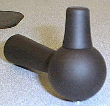
This is a picture of my first initial ear design. This one was pretty
bad and I did not persue it.
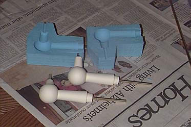
This is my second ear design which utilized a flexible drive mechanism.
The flexible shaft was inserted into the mold and the ear was cast
in one piece around the driveshaft sleeve. This design became
slightly jerky over time as the flexible shaft began to work harden
(very slight, but I was not happy with it). Also this required
an external drive motor to be mounted within the radar section which
was not preferable. The shape of the ear was greatly improved
over the original design.
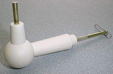
Another shot of the completed flexible drive ear.
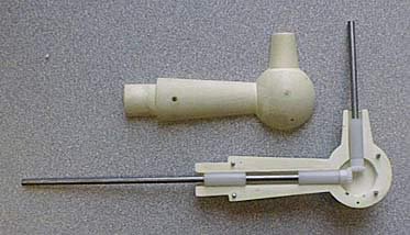
This design started off with a new ear shape and replaced the flexible
shaft drive with a gear drive. This method cured the jerky
motion, but still required an external motor and used up valuable
radar section space. This design would have been a kit where you
install the gear train and bushings and glue the halves together.
Unfortunately this design was cut short when my briefcase was stolen
with my ear inside.
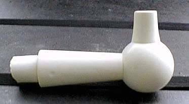
This is my final ear design which is solid resin. These can
be used as-is or motorized using a tiny gearhead motor that fit
into the vertical portion of the ear. This is my preferred
method since its simple, self-contained, reliable, and has a smooth
rotation.
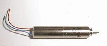
This is a picture of the gearhead motor I used inside my ear.
Its 7mm in diameter (about a 1Ú4").
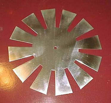
This is the aluminum spinner I made after it has been polished to
a mirrored finish with a buffing wheel.
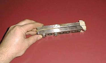
This is the tool I made up to bend the flaps of the spinner upwards.
By shipping the spinners flat it allows you to adjust the bend angle
so it will fit into the height of your bubble perfectly. I
have about 1/16" of space between the top of the spinner and
the bubble. It's two pieces of steel bolted together with
a piece of formica between them to match the thickness of
the spinner. Also notice the masking tape on the edges to
prevent marring the polished surface.
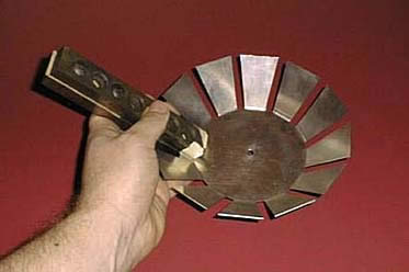
Spinner tool being used to bend flaps.
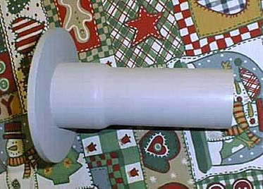
This is a side view of my neck. It is made from 1-1/2"
PVC electrical conduit and has the PVC neck flange welded onto the
pipe. The flare at the end of the pipe was perfect to house
the motor used to rotate the spinner and move the light antennas.
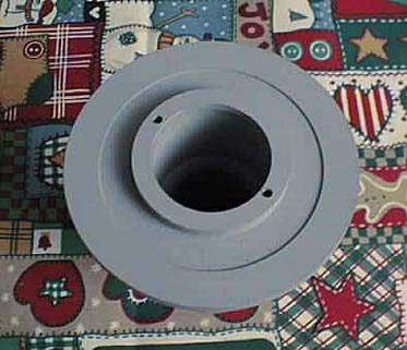
Top view of the neck assembly with holes drilled for mounting the
motor. Also notice the counterbore about 5/16" form the edge
of the flange - this was to accommodate the curved bottom plate.
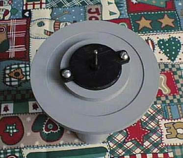
Top view of the neck assembly with motor installed.
|








 Scott
S. ( B9-0058 )


