


 |
|


| Robot Reference->Construction Tips->Neon & Audio Circuit | |||
Neon power supply with audio interface Submitted by Joe F. B9-0316
Download these Instructions in Word (.doc) format
WARNING Neon power supplies operate at high voltages that are LETHAL. YOU MUST observe all safety precautions associated with live electrical circuits. If you are unsure of or unfamiliar with high voltage electrical practices DO NOT CONSTRUCT THESE CIRCUITS. The author and distributor(s) of this information accept no liability
for injury or death and / or collateral or property damage arising
from the use, or inability to use this information. Use of the information contained herein constitutes your acceptance of the above disclaimer. The above in a nutshell: If you attempt to build any of these circuits,
either as shown or modified in any way and you hurt or kill yourself
(or anyone else) and / or burn down the house, your Robot or a grade
school, orphanage, children’s hospital etc,
Basic theory of operation:
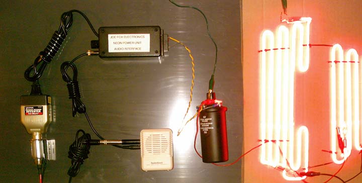
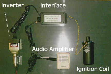
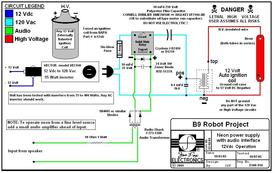
The solid-state relay is used to switch the 120 Volts from the inverter to the ignition coil. The solid-state relay is controlled from an audio source. The audio is sampled either directly from the speaker terminals or from a small audio amplifier (100mW or more) that is fed from the same audio source as the speaker’s amplifier. The second method is preferable since it allows independent control of the neon flashing threshold and speaker volume. The audio transformer steps up the audio sample. The stepped up audio voltage is AC. The 1N4005 diodes rectify the AC to the DC required to operate the relay. The Zener diode limits the applied DC voltage to protect the relay input. The limiting action allows the relay to be driven harder, providing cleaner switching of the relay i.e. it’s either full on or full off. The capacitor across the relay’s coil filters the DC signal and sets the syllabic rate (how fast the neon can flash). This filtering action insures the neon flashes on whole words and not a series of rapid flashes in time with the audio peaks. The capacitor in series with the ignition coil limits the AC current through the coils primary winding to prevent overloading the inverter or damaging the ignition coil from over current. The capacitor helps shape the AC current into sharp spikes that are more efficient at driving the ignition coil. The capacitor across the ignition coil primary increases the high voltage generated in the secondary and suppresses the transient voltages or spikes that are generated by the ignition coil primary. This helps protect the solid-state relay as well as the inverter in the DC version and the dimmer in the AC version. Notes on the 120 Volt AC version: At first glance, you may wonder why this version includes the dimmer and incandescent lamp. You might wonder why you couldn’t just operate the circuit directly from the 120 Volt AC line? The answer lies with the use of an ignition coil to supply the high voltage. Unlike a transformer designed for operation from the AC line, ignition coils are designed to operate on pulses. They depend on the rapid collapse of the magnetic field that occurs within the coil when the current is abruptly cut off. (Such as when the points open on a distributor for those of you old enough to remember cars before electronic ignition) If you study the waveforms of the AC current from various sources you will see why household current doesn’t work.
Lastly, The incandescent lamp across the dimmer is for functionality and
not as an indicator of any kind. Lamp dimmers are designed to operate
on purely resistive loads only. This circuit appears too inductive
for the dimmer to function properly. The dimmer does allow considerable adjustment of brightness but is primarily adjusted to provide complete stability of illumination. (no flicker) Good luck, WORK SAFELY! I would be glad to hear from anyone using these circuits.
|
|||
 Neon
& Audio Circuit
Neon
& Audio Circuit