


 |
|


| Robot Reference->Construction Tips->Light Flasher Circuit | |||
I have to do things the hard way. Rather than using incandescent flashing lamps, I built a circuit to flash either LEDs or incandescent lamps. The basic circuit I used is this:
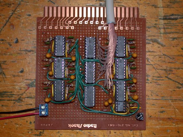
It's built around the common 555 timer chip, running in astable mode. According to this calculator, it should flash at a rate of 1.25Hz, with an on time of .326 seconds and an off time of .471 seconds (duty cycle is 40.9%). I originally had a pair of 100K variable resistors installed in place of the 47K and 68K fixed resistors to experiment with different values until I got something I liked. The .01uf capacitor connected between pins 4 and 8 and ground should be connected as close to pin 8 as possible. The 10uf capacitor is the tantalum variety. You should calculate the value of the LED current limiting resistor according to your LED's forward voltage and current requirements. I built a circuit on an old Radio Shack prototype board scrounged from my junk box to run the 12 belly lights and the two chest lights. The belly lights all use the same value resistors and capacitor, but because of the allowable tolerance in component manufacture, they all flash at slightly different rates. I elected to make the two chest lights flash alternately, but at a slower rate than in The Reluctant Stowaway. Controller
Schematic The actual circuit uses TLC556 Dual CMOS Timer chips, which have two complete timer circuits on board. While the 556 will provide enough current to drive LEDs, I ran the timer outputs through a pair of ULN2004A 7 transistor darlington arrays to provide enough drive for either LEDs or incandescent lamps. The ULN2004A also provides a convenient pin (9) which you can ground to turn on all the outputs simultaneously, as a "lamp test". The controller as built used 6 TLC556 dual timers, 2 ULN2004A darlington arrays, and a TLC555 single timer and a CD4013BE Dual D-Type Flip Flop (for the alternating chest lights). The speed of the chest lights can be varied by a trimpot. The schematics were drawn with Xcircuit, an open source schematic drawing and capture program, mainly for the Unix world. It can generate netlists for SPICE and PCB, another open source program for designing boards. For the 12 belly lights and 2 chest lights, I used super bright 12V LEDs in a BA9S miniature bayonet base. They recommend that you use the same color LED as the lens, so I got an assortment of white, red, green, amber, and blue LEDs to match my lens colors. The LEDs have an internal resistor for 12V operation, so all you have to do is make sure your sockets are wired for center pin positive, and pop them in. With all 14 LEDs lit, this circuit only draws about 300 milliamps. If you want to dim the bulbs a bit, you can reduce the voltage, and it won't affect the flash rate. Light
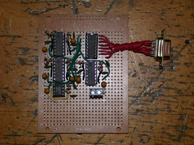
Rod Controller Schematic To make the 7 LED lamps on the light rods flash, I put together another controller, with 3 TLC556 dual timers, 1 TLC555 single timer and 1 ULN2004A darlington array. This board will be mounted in the brain, and connect to the light rods through a hole in the brain cup. Please note that with this circuit, the common connection to the lamps is the positive side. If you're using incandescant bulbs, this isn't a problem. If you're going top use LEDs in the light rods, like I did, you should connect the cathode to the center pin, rather than the anode. For more information about my circuits, including movies and pictures of my home made LED lamps, see my Electronics and Electrical page. Mike Loewen B9-0014 |
|||
 Homebrew
Light Flasher Circuit
Homebrew
Light Flasher Circuit