06/30/2012
Completion of Greg's
Radar Kit
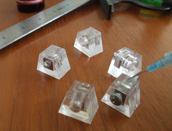
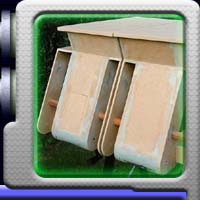
These
are the foot pads which will connect the radar to the bearing
plate on the collar. They are made up of a clever system of
acrylic layers which trap the locking nut inside. These layers
are solvent welded together to form a solid block.
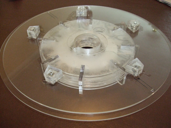
This
shows the five foot pads solvent welded to the underside of
the top plate of the radar section.
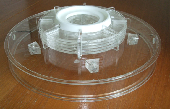
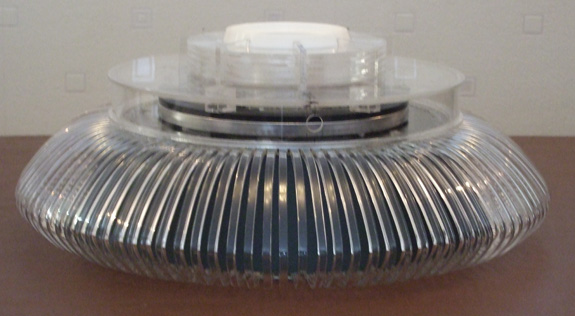
The
completed radar section. I'm really pleased with the way it
has turned out thanks to Greg's
comprehensive instruction sheets.
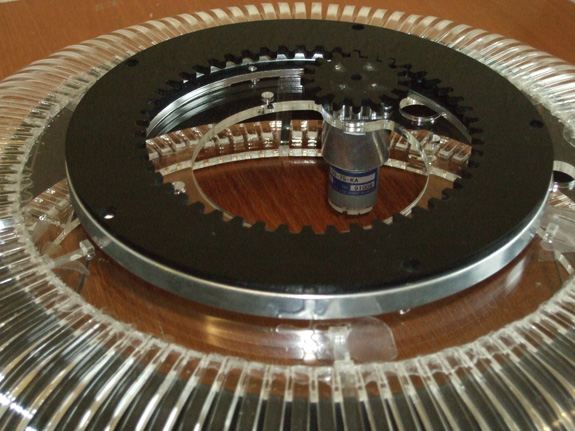
This
is Greg's radar animation kit and motor assembled onto the collar
section.
This
shows the radar connected to the bearing plate and collar section.
All that is needed now is to fit the earposts and prime the
radar section.
06/18/2012
Radar Kit Update
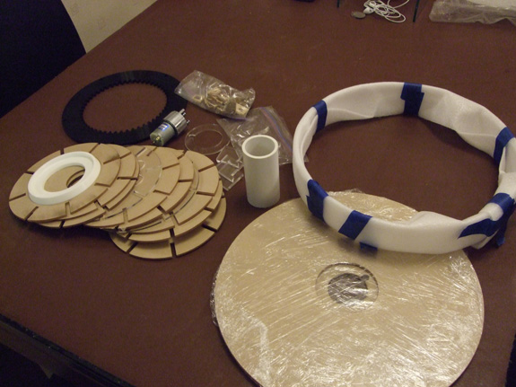
I
received Greg's radar kit along with the animation kit and here
it is all laid out. I'm looking forward to getting started.
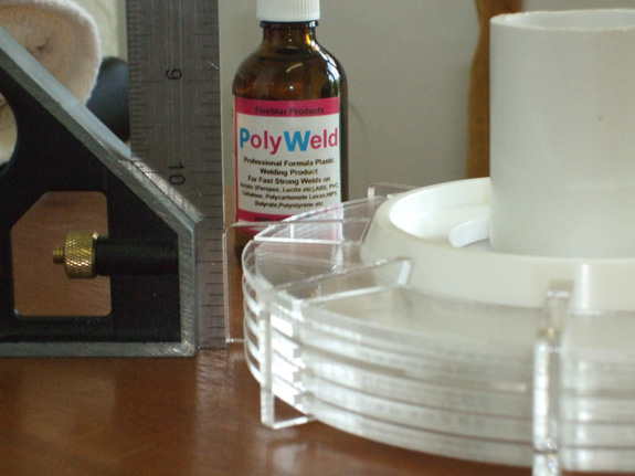
This
is the clutch pack assembly. I'm using a square edge to make
sure everything is absolutely vertical. I'm also using Polyweld,
this is a solvent solution especially for solvent welding acrylic.
It is the only type I could find over here in the UK and it
is the water thin type. You just assemble your parts and then
inject the solution along the join. Capillary action draws the
solution into the join and welds the two surfaces together.
You must make sure your parts are correctly aligned because
when this stuff sets which is literally in seconds there is
no going back. If any UK builders need this solution you can
buy it from www.shop4glue.com
at a very reasonable price.
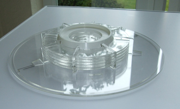
This
is the clutch assembly all welded and joined to the top section
of the radar. Next step is to join it with the radar sides and
bottom section.
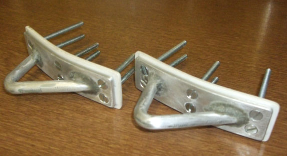
06/10/2011
Here
is one of my homemade aluminum torso hooks ready to be primed
mounted on the torso.
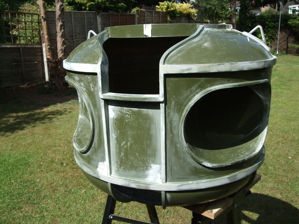
Here's
the torso section in the middle of prepping. I'm thinking of
going with a smooth finish, so there's lots of bondo filling
and sanding to make sure the surface is at it's best for painting.
I'm actually really enjoying this part, I'm concentrating on
one area of the torso at a time and getting it right before
moving onto the next area and then afterwards going back and
checking again.

04/18/2009
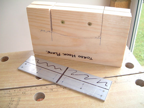
Here
we have the wooden mold I made with the aluminum plate marked
out ready for cutting forming to the correct curve for it to
fit on the B9's shoulders.
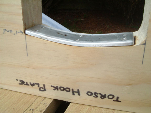
After
heating the aluminum plate using the gas ring on our cooker,
I placed the plate in the mold and pressed down.
The
aluminum was very pliable and took little effort to form. I
left it in the mold to cool and then did the same for the other
torso plate.
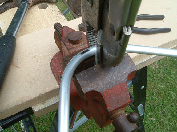
With
the hooks themselves, I heating them the same way and using
a vice and pliers bent them to the required angle.
After they had cooled I cut them to the required size and angle,
and drilled and tapped the ends so the could be screwed to the
plates.
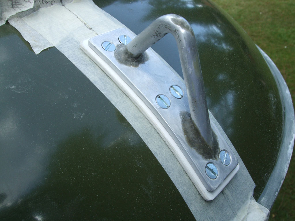
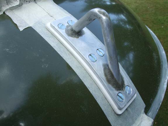
Here
are the finished torso hooks. I've used a filler called 'Chenical
Metal' around the area where the hooks meet the plate to simulate
a welding seam and it has worked out very well.
As I want to be as authentic as possible, I've also gone for
the six screw fixing as shown in the photos on the club site.
I will post a photo of them fixed to the torso shortly.
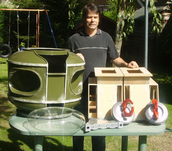
08/28/2006
This
is a picture of me doing an impression from the episode 'Wreck
of the Robot' minus a few parts. Seriously though, this
is a picture of the parts I've so far accumulated towards my
B9 project. The treads I built myself, the torso, donut,
bubble and brain I bought from the club. The claws and
aluminium wrists I purchased from a fellow English member and
builder, Paul F. who upgraded
his.
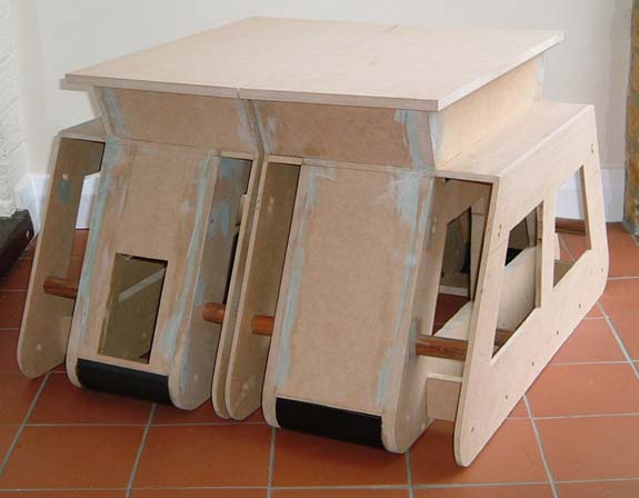
03/04/2005
Here
are my MDF treadsections in their raw state. You may notice
two sets of axle holes in the upper part of the treads. I
redrilled the upper holes as Craig's recommendation for a more
accurate positioning of the upper set of wheels. Now all
I need to do is fill in the old holes I originally drilled.
I used plastic drain pipe cut into four pieces for the
toe sections. The diameter was a shade smaller, so I softened
the plastic in boiling water and carefully flattened them slightly
to achieve the correct curvature before gluing them in place.
All I need to do now is feather in all the joins and gaps with
filler.
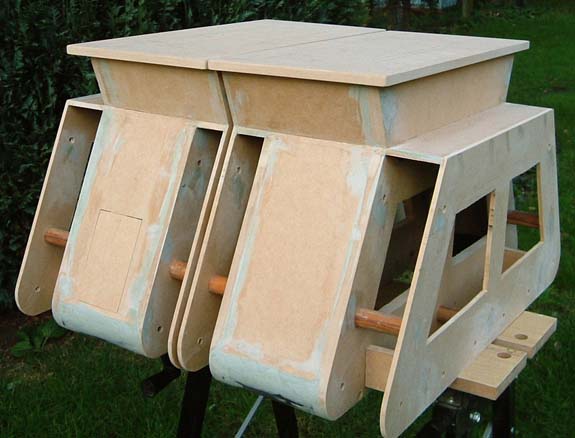
Here
they are filled and sanded. The soil sampler door is in
postion. I plan to cover the front and backs of the treads
with sheet styrene. This is because I want to add the
little detail of the arcs to the top of each wheel housing,
and also I hope it will cover any cracks in the joins should
they develope over time. My next stage will be fitting
the knee plates and also I'm going to attempt at making my own
fibreglass knee bellows.


 Steve
B. ( B9-0102 )
Steve
B. ( B9-0102 )