 Scott
S. ( B9-0058 ) Scott
S. ( B9-0058 )
Light
Rods & Wrists
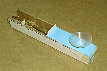
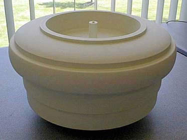
This is the mold used to cast resin around my light antenna assembly.
The antennas re made by soldering the light sockets to 1Ú4"
brass tube and casting a very thin layer of resin around them.
The outside of the tube is used as a ground conductor which only
requires one wire inside the light antenna.
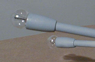
Close-up of the completed light antenna. Notice how the cast
resin base mates right up against the lightbulb - no unsightly gap!
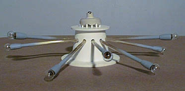
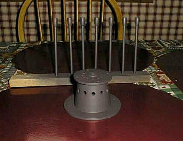
View of the light antenna assembly with the cam and pushrods installed.
Notice that cam is mounted inside the brain and used push rods to
move the light antennas. The pushrods isolate the rotational
forces from the cam being transferred to the light antennas causing
side to side movement. The cam design is not the final design.
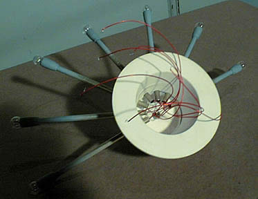
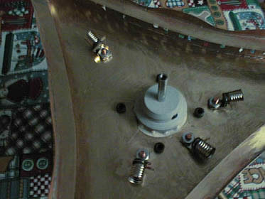
Bottom view of the light antenna assembly. Each light antenna
has a tiny hole drilled through it in which a wire passes.
This wire acts as the hinge and also the ground for the lights.
There is a groove cut into the brain cup for the hinge wire to snap
into. This minimizes the wires inside the light antenna and
provides a smoother motion (less wires to flex during motion).
Not shown is the shaft that connects the spinner, passes through
the cam, and mounts to the motor shaft in the neck.
Light antennas and brain cup painted and waiting final assembly.
This shot shows the interior of my brain. I added two more
lights in the rear after this picture was taken. I mounted
the light sockets using studs that were soldered onto the base of
the brain. This allows the light sockets to be removed easily
and light partions to be added to segregate the lighted areas in
the brain. The cam is in place and the spinner mounts onto
the top of the shaft using a machine screw.
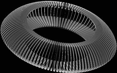
This is a 3D depiction of my collar segments form the CAD file.
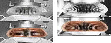
This is a composite picture that was used to verify my collar design
I did for Dewey. The copper colored collar is my actual rendered
cad file. This method did not provide a lot of detail, but
did help verify that it "looked right".
Second attempt at making the wrist, this time I took 50 pictures
of the real robot and digitally measured the wrists using the real
robot from the screen captures. This is by no means an exact
science because of camera angles and distortion, so you need lots
of reference pictures. The final result is "does it look right"?
This wrist has the correct proportions and a flat center as the
original robot did (it is not curved). This was not the final
version of the wrist shape though. Always some more tweaking to
be done! I also used a material called "Butterboard"
or "NC proofboard" to make this mater. It's a resin
like material and is lightweight and dimensionally stable.
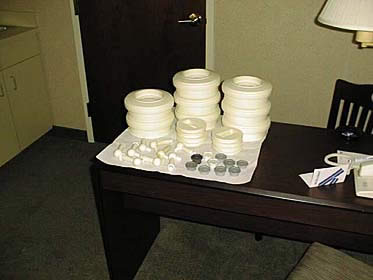
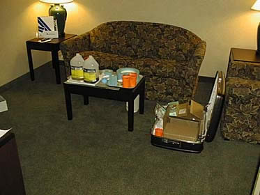
Have some extra time while traveling on business? Take your
molds and have some resin delivered. Just don't spill the
resin on the furniture!
|